This will guide you through the process of installing coreboot on the Lenovo t440p with a Raspberry Pi 3 and some of the
accessories that are sold with a CH341a.
Using a CH341a is discouraged because it has 5V logic levels on data lines instead of the recommended 3.3V and therefore will damage your SPI flash and also the southbridge that it’s connected to, plus anything else that it’s connected to.
A Rasperry Pi instead has the recommended 3.3V and hence it can be used instead of the CH341a.
Even with all these precautions, there is always a chance that this will brick your laptop. Do this at your own risk.
- Introduction
- Materials
- Update the Embedded Controller on the T440p
- Prepare the Raspberry Pi
- Connect the Raspberry Pi to the Clip.
- Prepare the Lenovo ThinkPad T440p
- Read the Flash Chip
- Obtain The Original ROM
- Build Blobs
- Configure Coreboot
- Building and flashing
- Back to the Raspberry Pi: Flash Coreboot
- Boot
- What To Do From Here
- Acknowledgements
- Sources
Introduction
The Lenovo ThinkPad t440p is a great laptop that I bought years ago for the incredible upgradability that it offers, which makes it the perfect workstation for devs and tinkerers.
One of the options I was extremely excited about is the possibility to add a custom BIOS. I wanted to replace the BIOS because Lenovo’s default BIOS comes with a Wi-Fi whitelist that would prevent me from upgrading the existing Wi-Fi card to a new, more powerful one; so I thought I might as well install a (mostly) Open Source BIOS.
coreboot, according to its Wikipedia page, is a software project aimed at
replacing proprietary firmware (BIOS or UEFI) found in most computers with a lightweight firmware designed to perform only
the minimum number of tasks necessary to load and run a modern 32-bit or 64-bit operating system. Since coreboot initializes
the bare hardware, it must be ported to every chipset and motherboard that it supports. As a result, coreboot is available only
for a limited number of hardware platforms and motherboard models.
I quickly found a nice video on YouTube detailing how to do it. In laymen terms, I would have to connect the BIOS chip to another computer via a flasher and a “clip”; the flasher and clip would transmit electric impulses to the BIOS chip, and these electric impulses would write (“flash”) the new BIOS onto the chip.
I soon found (and bought) the flasher I needed: a CH341a.
With that done, I thought I was ready to flash my new BIOS. Then I finally realized that using the CH341a - the flasher I bought - was discouraged.
According to the Libreboot documentation
(Libreboot being one of the coreboot variants partly free of proprietary blobs), using a CH341a is discouraged
because this flasher has 5V logic levels on data lines instead of the recommended 3.3V and therefore will damage the SPI flash and also the
southbridge that it’s connected to, plus anything else that it’s connected to.
This was disheartening. I’m not an expert on this topic and the CH341a was the only flasher I knew thanks to the guides I found. Despite my best efforts I couldn’t find a flasher that would use the recommended 3.3V. In fact, the CH341a was the only flasher I could find. It’s crazy how popular this flasher is considering how dangerous it can be! Other guides would either not mention different flashers, or mention flashers that I couldn’t find on Amazon.
It should be noted that it could have been possible to make my flasher send 3.3V instead of 5V if I had applied this fix and bypassed the 1117-3.3V regulator. However, as I mentioned before, I’m not an expert on this topic and I have a very rough idea of what “bypassing the 1117-3.3V regulator” means; plus, achieving that requires soldering skills that, sadly, I don’t have. So this option was also out of the question.
To make things more complicated, I really wanted to reuse the accessories the CH341a came with: while using the CH341a is undoubtedly dangerous, as far as I could tell the accessories were just fine and could be safely used for flashing a coreboot BIOS. I already wasted some money on the flasher itself, I didn’t want to buy some new accessories too!
Then I finally found the most popular flasher around: the Raspberry Pi!
Sounds crazy, uh? But the Raspberry Pi is very suitable for this kind of thing as it has a SPI interface and is able to run Linux. And, as luck would have it, I already had a Rasperry Pi 3 lying around!
I quickly found a couple of guides on how to flash a BIOS chip with a Raspberry Pi. I still had the video guide I mentioned before, plus the (written) guide that was used for that video. All I had to do was mixing them all together.
So here you have it!
Note
Even with all these precautions, there is always a chance that this will brick your laptop. Do this at your own risk.
Materials
- Lenovo ThinkPad T440p
- CH341a SPI flasher - only the accessories. As I previously mentioned, I used this one
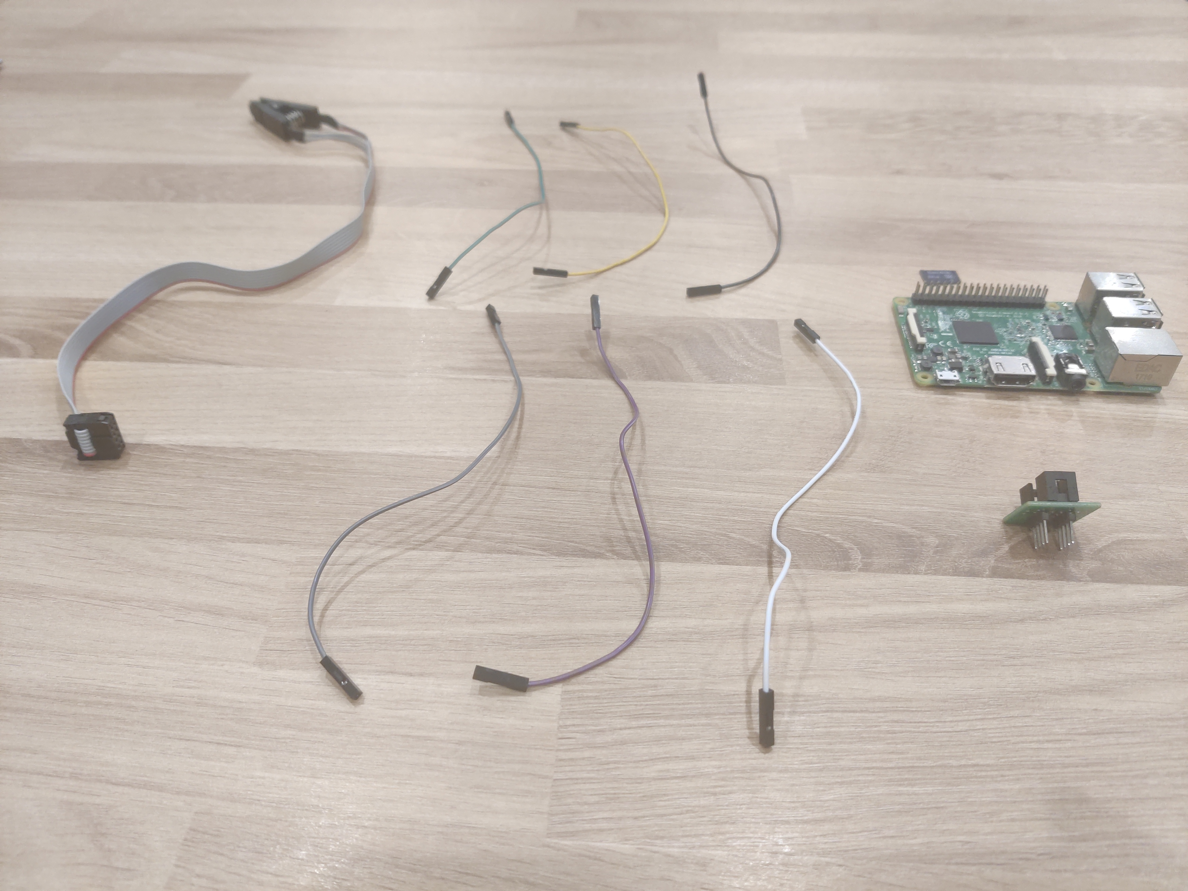
- Raspberry Pi - I’ve used a Raspberry Pi 3 Model B, but you should be fine with any Rasperry Pi really
- Female to Female Breadboard Jumper Cables, also known as Dupont wires - I used these
- Phillips Screwdriver for dissassembling the Lenovo ThinkPad t440p
- (Potentially) Another PC, preferably running a Linux Distro - we are going to need this to build coreboot: the Raspberry Pi 3 doesn’t have enough horsepower to pull this off. If you’re using a newer Raspberry Pi your mileage may vary. You could build coreboot on the T440p, just make sure that you build coreboot and move the resulting artifacts to the Raspberry Pi or its SD card before you disassemble the T440p
Update the Embedded Controller on the T440p
It is a good idea to update the Embedded Controller to the latest version. The easiest way to do this is install the latest version of the factory bios. Coreboot is unable to touch the EC. You will be unable to update it after flashing unless you revert to the factory bios.
Prepare the Raspberry Pi
Prepare your Raspberry Pi with the latest version of Raspberry Pi OS. I got mine from here.
Once that is done, boot your Raspberry Pi and update the OS with:
sudo apt update
sudo apt dist-upgrade
In order to read/write to the bios chip you need to enable some kernel modules.
Access the raspberry pi config utility:
sudo raspi-configIn raspi-config select Interfacing options
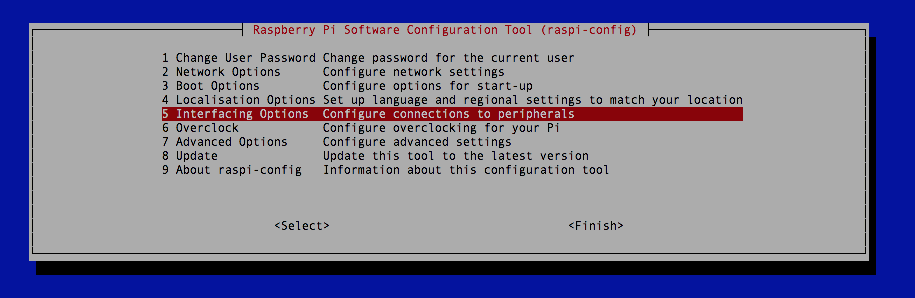
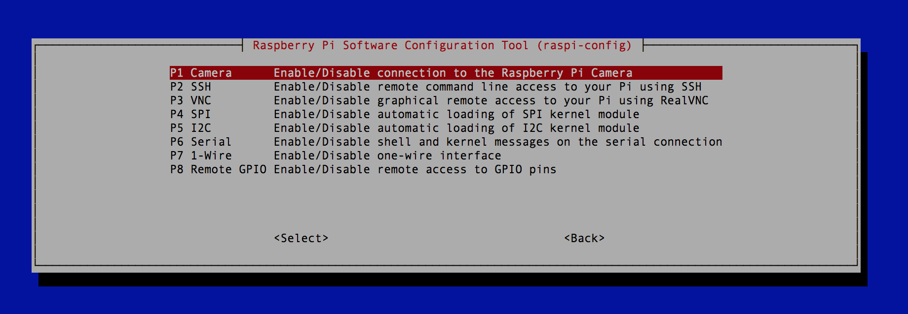
Under interface options enable:
- P4 SPI
- P5 I2C
Make a directory in your home dir to work in and store the factory images. For this example I will be calling it t4:
mkdir ~/t4Connect the Raspberry Pi to the Clip.
Power off the Pi.
Note: it is important to power off the Pi before you connect it to the BIOS chip. Failing to do so may damage your motherboard and brick your laptop, so don’t forget to POWER YOUR PI OFF!
Use the 6 female to female wire to connect the clip to the Pi:
| Raspberry Pi | CH341a SPI Socket |
|---|---|
| Pi 17 | BIOS 8 |
| Pi 19 | BIOS 5 |
| Pi 21 | BIOS 2 |
| Pi 23 | BIOS 6 |
| Pi 24 | BIOS 1 |
| Pi 25 | BIOS 4 |
I’ve used this accessory from the CH341a SPI flasher. As you can see these numbers correspond to the numbers in the table above,
so all the BIOS N in the table above correspond to the numbers on this socket:
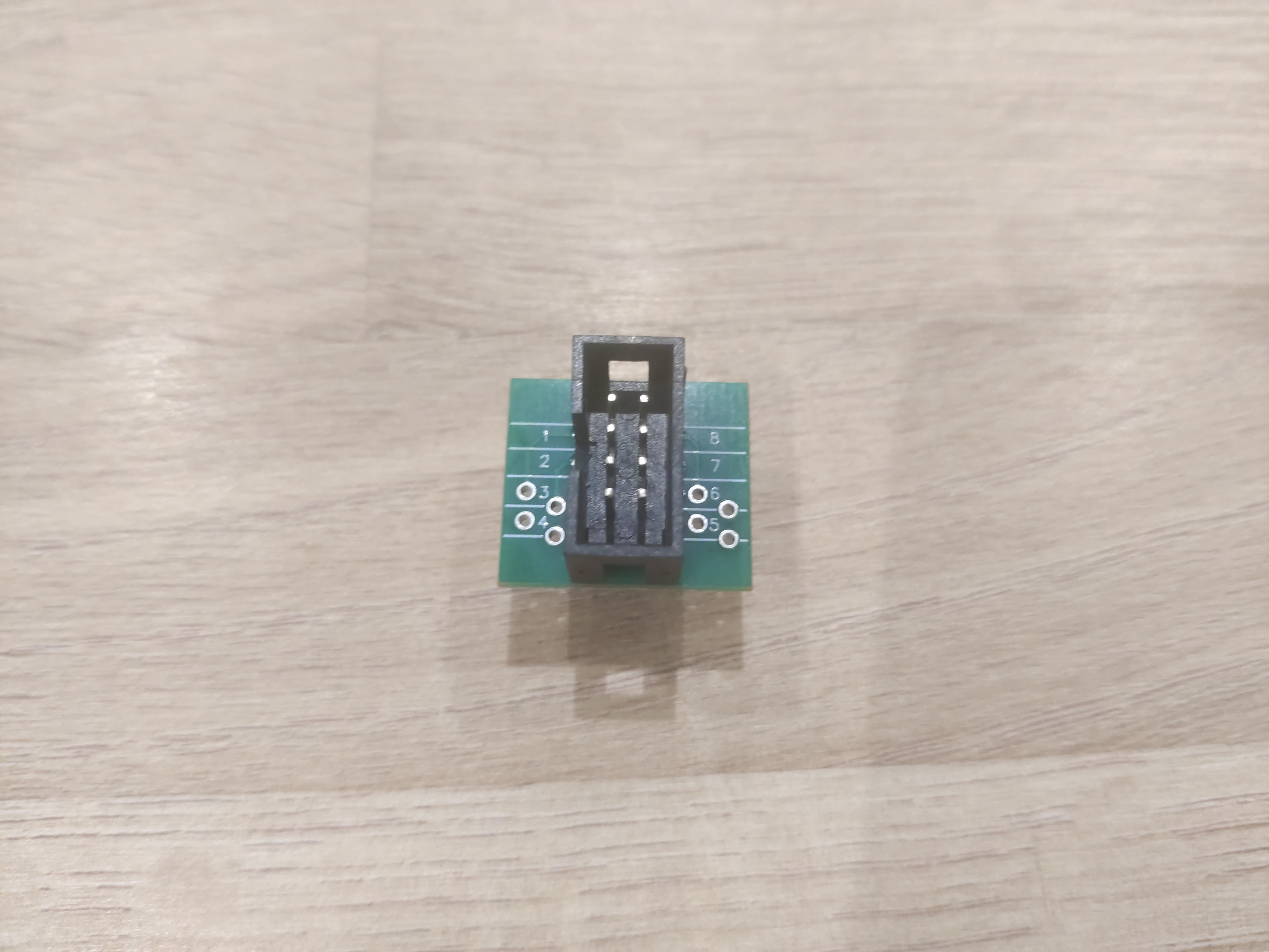
However, we cannot use the top of the socket: that’s for the cable that is connected to the CH341a SPI clip.
We will have to use the bottom pins:
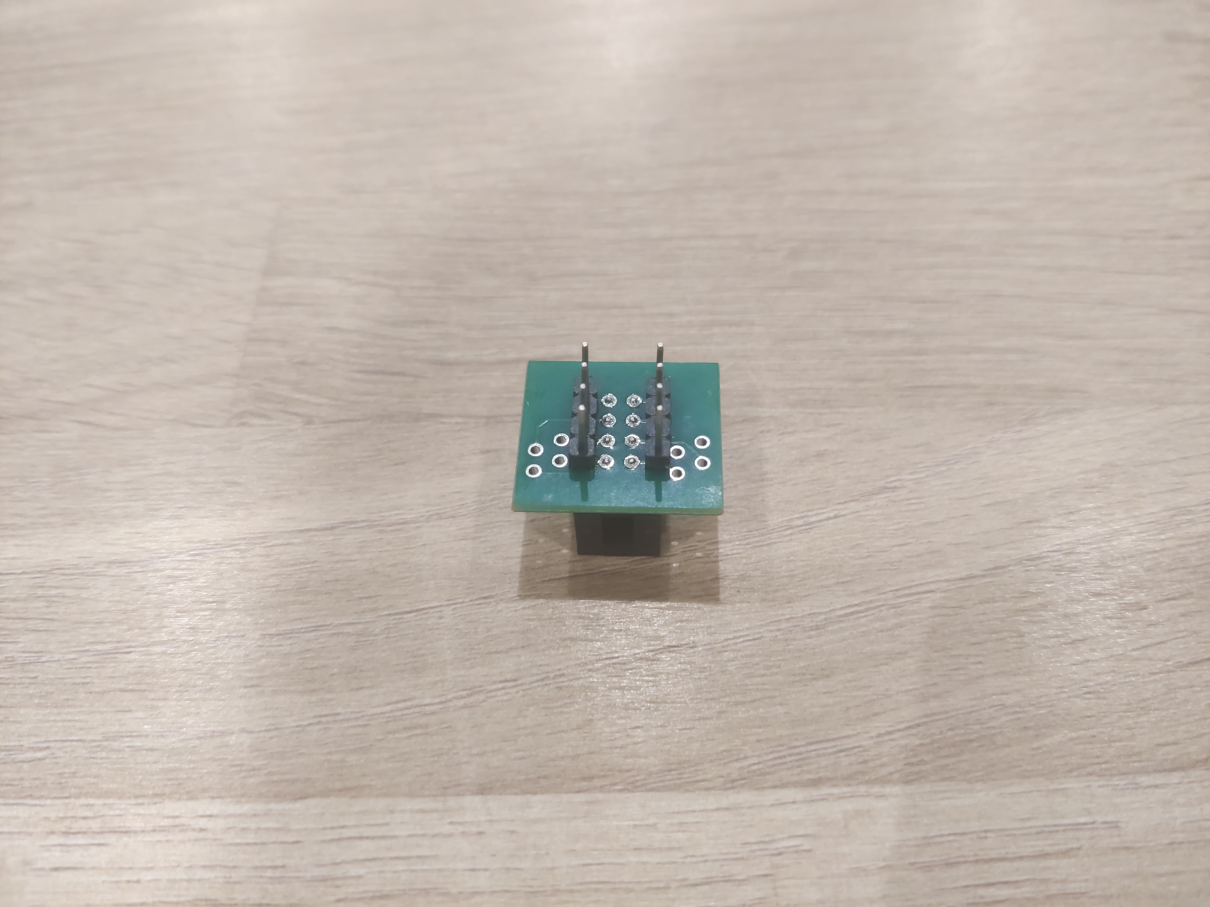
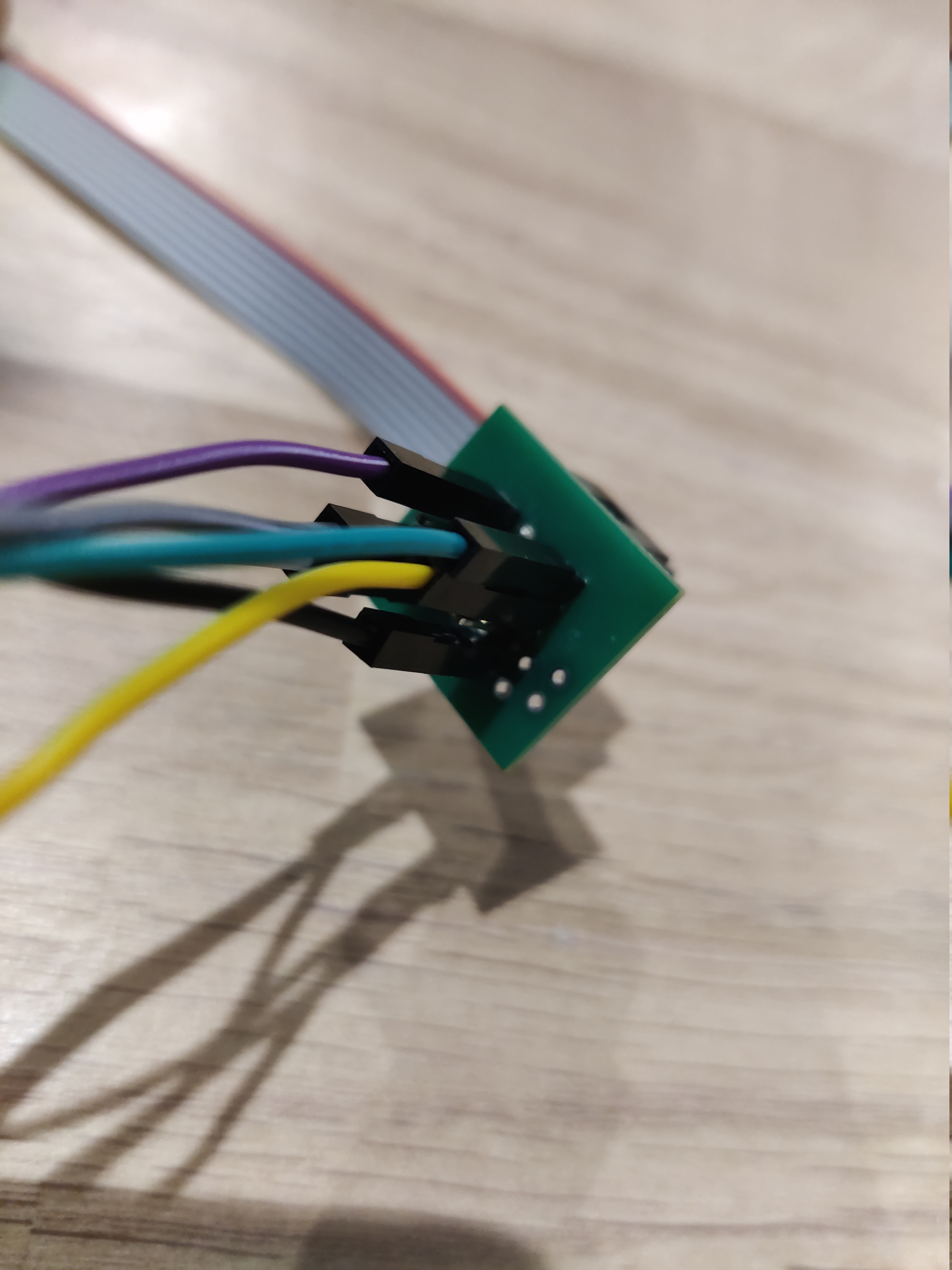
In the end it should look like this:
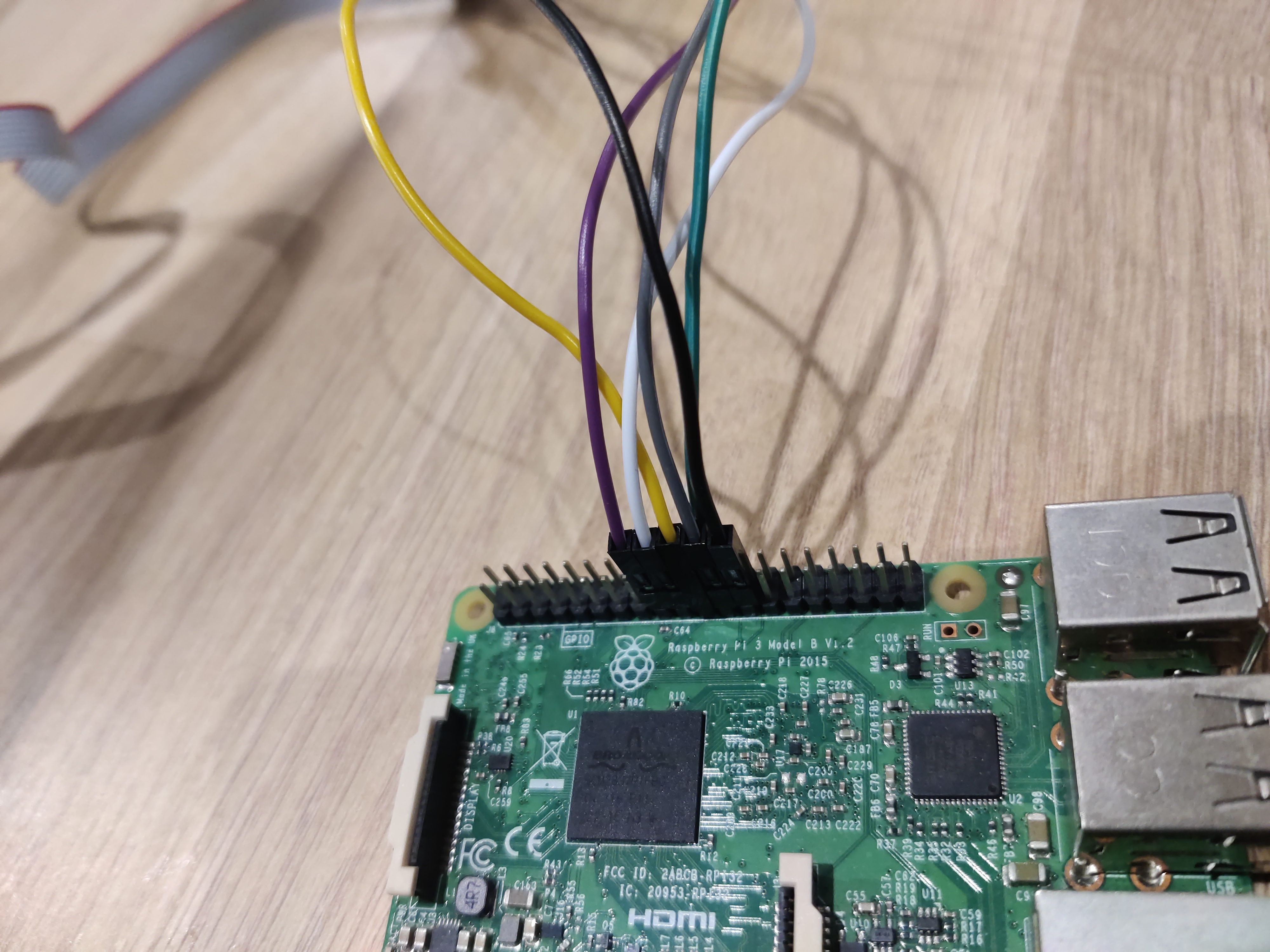
For the Raspberry Pi, use this pinout diagram:
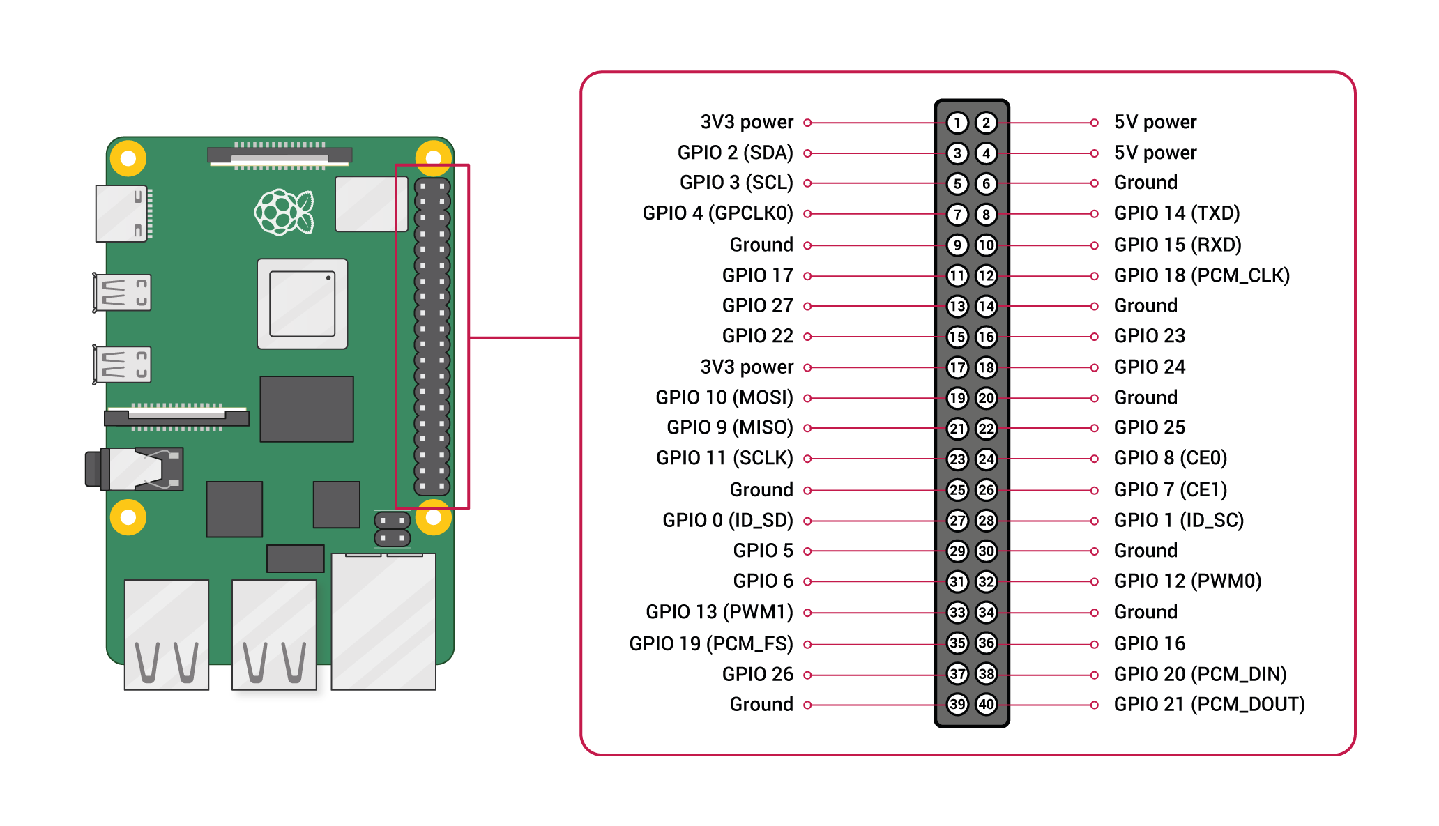
So in the table above all the Pi NN refer to the numbers on this diagram.
Pins 3 and 7 on the BIOS are not used.
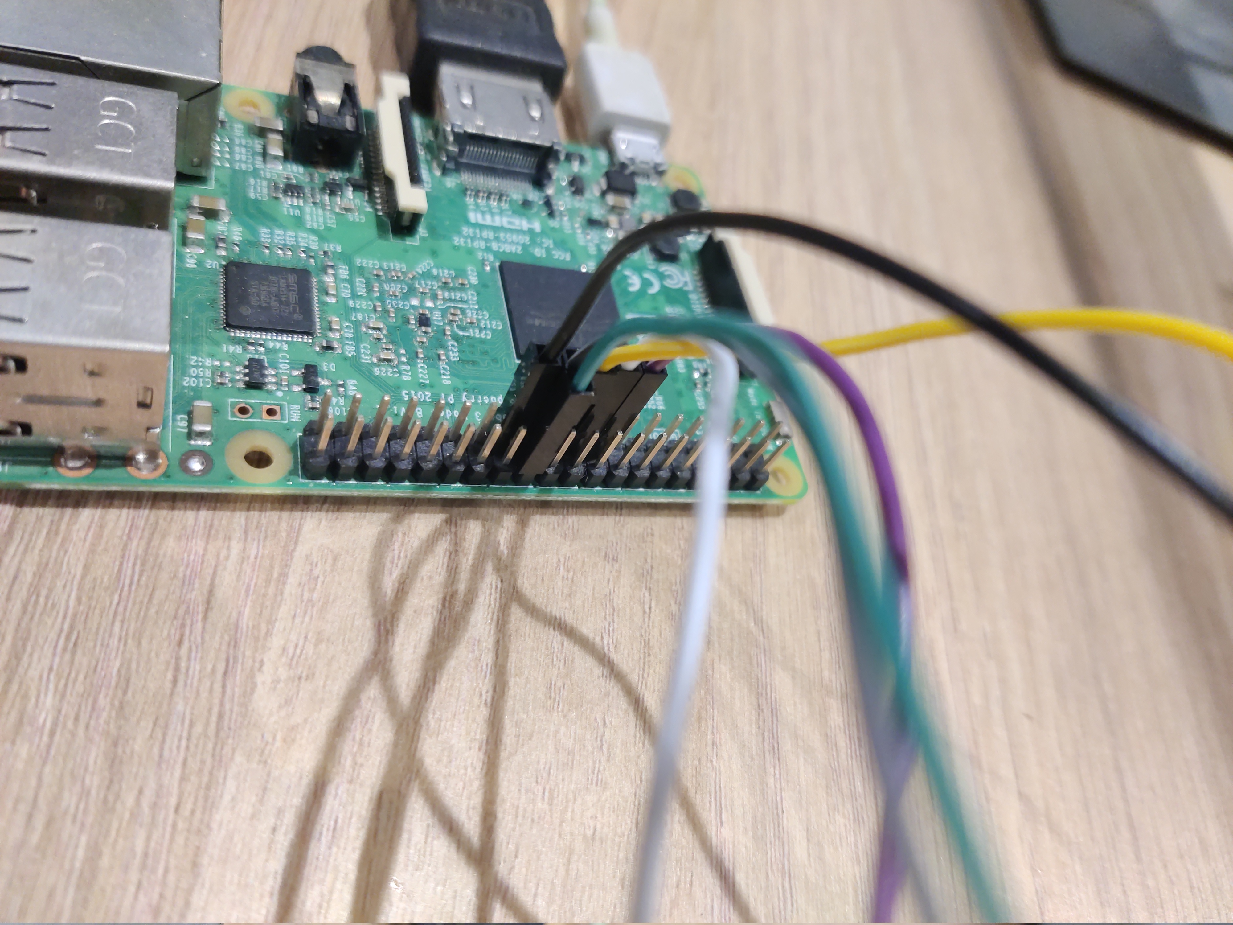
In the end, your Raspberry Pi should look like this:
Finally, connect the clip to the socket. It can only connect in one way.
Prepare the Lenovo ThinkPad T440p
Take out the battery and unscrew the access door of your Lenovo ThinkPad T440p.
Take it apart until you see both EEPROM-chips next to the RAM:
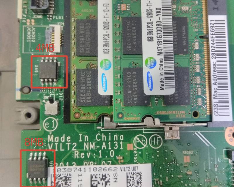
Now you can connect the clip to the 4MB (also called top) BIOS chip.
Read the Flash Chip
Power on the Pi.
Open a terminal and move to the roms folder we created before:
cd ~/work/romsTo read and write the chip you will need to use a program called Flashrom. Let’s first make sure it is installed:
sudo apt install flashromUse flashrom to probe the chip and make sure it is connected. Use the -c option to specify your flash chip. Make sure to enter everything between the quotes:
flashrom -p linux_spi:dev=/dev/spidev0.0,spispeed=512 -c "W25Q32BV/W25Q32CV/W25Q32DV"Note: if you get an error it may be due to a faulty connection; the clip may not be properly in place. Try to reconnect the clip in this way: power off your Raspberry Pi; disconnect the clip; connect it again; turn on your Raspberry Pi.
If no error message is displayed, we are ready to read the flash chip. We are going to take two reads and then compare the two. Each read will take some time depending on the chip. It could even take between 30 and 45 min. Don’t worry if it seems like the Pi is hung.
flashrom -p linux_spi:dev=/dev/spidev0.0,spispeed=512 -c "W25Q32BV/W25Q32CV/W25Q32DV" -r 4mb_backup1.bin
flashrom -p linux_spi:dev=/dev/spidev0.0,spispeed=512 -c "W25Q32BV/W25Q32CV/W25Q32DV" -r 4mb_backup2.bin
Next you want to compare the 2 files to make sure you had a good read / connections:
diff 4mb_backup1.bin 4mb_backup2.binOnly if diff outputs nothing continue - else retry.
Power off the Pi, disconnect the clip from the top chip and connect it to the bottom (8MB) chip, then turn the Pi on again.
Open a terminal and move to the roms folder we created before:
cd ~/work/romsOnce again, use flashrom to probe the chip and make sure it is connected:
flashrom -p linux_spi:dev=/dev/spidev0.0,spispeed=512 -c "W25Q64BV/W25Q64CV/W25Q64FV"If no error message is displayed, we are ready to read the flash chip. We are going to take two reads and then compare the two:
flashrom -p linux_spi:dev=/dev/spidev0.0,spispeed=512 -c "W25Q64BV/W25Q64CV/W25Q64FV" -r 8mb_backup1.bin
flashrom -p linux_spi:dev=/dev/spidev0.0,spispeed=512 -c "W25Q64BV/W25Q64CV/W25Q64FV" -r 8mb_backup2.bin
diff 8mb_backup1.bin 8mb_backup2.bin
Only if diff outputs nothing continue - else retry.
Obtain The Original ROM
Combine the files to one ROM (the System sees these chips combined anyway):
cat 8mb_backup1.bin 4mb_backup1.bin > t440p-original.romSAVE THE ROM SOMEWHERE SAFE and in multiple locations!
Build Blobs
It’s now time to switch to your other PC. Remember? The PC that is preferably running a Linux Distro. We are going to need this PC to build coreboot: the Raspberry Pi 3 doesn’t have enough horsepower to pull this off.
Turn on that PC.
Firstly, we are going to need the files that you have on your Pi. Turn off your Pi, then insert your SD card on your PC; if you can’t, then just transfer the files to your PC in a different way.
Then install the dependencies needed to build coreboot:
sudo apt install git build-essential gnat flex bison libncurses5-dev wget zlib1g-dev base-devel curl gcc-ada ncurses zlib nasm sharutils unzip flashromWe are going to create the same folders we had on the Pi, just for consistency’s sake.
Make a directory in your home dir to work in. For this example I will be calling it work. You will also want a directory to store the factory images. I will call that directory roms. You can do this in one line to save time:
mkdir -p ~/work/romsTransfer the roms you have extracted into this directory:
cd ~/work/roms
cp /path/to/your/rom .
Then move into the work directory:
cd ~/workDownload the latest version of coreboot:
cd ~
git clone https://review.coreboot.org/coreboot
Move into the coreboot directory:
cd corebootDownload the required submodules:
git submodule update --init --checkoutBuild the ifd tool. This will be used to split the factory bios into it’s different regions.
cd util/ifdtool && makeUse the rom from before to export the blobs and move them to your roms folder:
./ifdtool -x ~/work/roms/t440p-original.rom
mv flashregion_0_flashdescriptor.bin ~/work/roms/ifd.bin
mv flashregion_2_intel_me.bin ~/work/roms/me.bin
mv flashregion_3_gbe.bin ~/work/roms/gbe.bin
Next, we need a mrc.bin file. We’ll obtain this blob from a haswell Chromebook firmware image (peppy in this case) but first we need to
build the cbfstool for extraction:
cd ~/coreboot
make -C util/cbfstool
cd util/chromeos
./crosfirmware.sh peppy
../cbfstool/cbfstool coreboot-*.bin extract -f mrc.bin -n mrc.bin -r RO_SECTION
mv mrc.bin ~/work/roms/mrc.bin
Configure Coreboot
You will have to configure coreboot before you can build it for you T440o.
You can either add this known working config to ~/coreboot/.config or you configure coreboot yourself via nconfig.
Easier Route: Preconfigured .config
go back to the coreboot folder and open .config in nano or vim:
cd ~/coreboot
nano .config
Paste this config and edit the path to the t4 folder to reflect your path. You will also have to change the username to yours:
CONFIG_USE_OPTION_TABLE=y
CONFIG_TIMESTAMPS_ON_CONSOLE=y
CONFIG_VENDOR_LENOVO=y
CONFIG_CBFS_SIZE=0x200000
CONFIG_LINEAR_FRAMEBUFFER_MAX_HEIGHT=1600
CONFIG_LINEAR_FRAMEBUFFER_MAX_WIDTH=2560
CONFIG_IFD_BIN_PATH="/home/dre/work/roms/ifd.bin"
CONFIG_ME_BIN_PATH="/home/dre/work/roms/me.bin"
CONFIG_GBE_BIN_PATH="/home/dre/work/roms/gbe.bin"
CONFIG_CONSOLE_CBMEM_BUFFER_SIZE=0x20000
CONFIG_TIANOCORE_BOOT_TIMEOUT=2
CONFIG_HAVE_IFD_BIN=y
CONFIG_BOARD_LENOVO_THINKPAD_T440P=y
CONFIG_HAVE_MRC=y
CONFIG_MRC_FILE="/home/dre/work/roms/mrc.bin"
CONFIG_UART_PCI_ADDR=0x0
CONFIG_VALIDATE_INTEL_DESCRIPTOR=y
CONFIG_H8_SUPPORT_BT_ON_WIFI=y
CONFIG_HAVE_ME_BIN=y
CONFIG_CHECK_ME=y
CONFIG_USE_ME_CLEANER=y
CONFIG_HAVE_GBE_BIN=y
CONFIG_SUBSYSTEM_VENDOR_ID=0x0000
CONFIG_SUBSYSTEM_DEVICE_ID=0x0000
CONFIG_I2C_TRANSFER_TIMEOUT_US=500000
CONFIG_SMMSTORE_SIZE=0x40000
CONFIG_DRIVERS_PS2_KEYBOARD=y
CONFIG_TPM_DEACTIVATE=y
CONFIG_SECURITY_CLEAR_DRAM_ON_REGULAR_BOOT=y
CONFIG_POST_IO_PORT=0x80
CONFIG_PAYLOAD_TIANOCORE=y
CONFIG_TIANOCORE_BOOT_MANAGER_ESCAPE=y
CONFIG_TIANOCORE_SD_MMC_TIMEOUT=1000
run nconfig to populate the other options and exit:
make nconfig(save with F6 and exit with F9)
Note: some of the config options are deprecated; I will try to update them soon
Harder Route: Your .config
Go back to the coreboot folder and run nconfig, select the device (Mainboard: Lenovo, Mainboard model: T440p, Chipset: add the blobs paths from before)
Then configure it to your liking:
cd ~/coreboot
make nconfig
(save with F6 and exit with F9)
Building and flashing
Time to compile!
First: build the gcc toolchain:
make crossgcc-i386 CPUS=Xwhere X is the number of threads your CPU has (e.g. 16) so please change it to your PC’s specs.
Then, build coreboot:
make iasl
make
Note: if you run into issues with Python you may need to run: sudo apt install python-is-python3
This will produce a file ~/coreboot/build/coreboot.rom.
Copy that file to your Pi, in your ~/work/roms directory. To be on the safe side, here I’m copying the whole build folder:
cp build/ /media/dre/rootfs/home/dre/work/coreboot/Back to the Raspberry Pi: Flash Coreboot
This is the last thing we needed to do on the PC. You can now turn this device off and insert the SD card back into your Raspberry Pi.
While we are at it, connect your Pi to the 4MB BIOS chip (top): we are going to need it soon.
With that done, power up your Pi.
We first need to split the built ROM for the 8MB chip (bottom) and the 4MB chip (top)
cd ~/coreboot/build
dd if=coreboot.rom of=bottom.rom bs=1M count=8
dd if=coreboot.rom of=top.rom bs=1M skip=8
With that done we are almost ready to flash. Before doing the actual flashing we are going to probe the chip, just like before. Run:
flashrom -p linux_spi:dev=/dev/spidev0.0,spispeed=512If probing didn’t give any error, run:
cd work/coreboot/build/
flashrom -p linux_spi:dev=/dev/spidev0.0,spispeed=512 -c "W25Q32FV" -w top.rom
Then, power off your Raspberry Pi and connect the clip to the 8MB BIOS chip (bottom):
sudo poweroffLike before, we are going to probe the BIOS chip before doing any flashing.
Turn on your Pi and run:
flashrom -p linux_spi:dev=/dev/spidev0.0,spispeed=512If probing didn’t give any error, run:
cd work/coreboot/build/
flashrom -p linux_spi:dev=/dev/spidev0.0,spispeed=512 -c "W25Q64BV/W25Q64CV/W25Q64FV" -w bottom.rom
Congrats! You have just flashed coreboot.
After the write is verified power off the Pi, remove the clip and reassemble the T440p.
It’s now time to…
Boot
and hope for the best ;-D
What To Do From Here
Update Process
Note: this section hasn’t been tested
Build a new coreboot ROM.
Then set the kernel to iomem=relaxed so it allows internal flashing.
In /etc/default/grub add iomem=relaxed to the space seperated list:
GRUB_CMDLINE_LINUX_DEFAULT="iomem=relaxed quit splash"Then apply the config:
sudo grub-mkconfig -o /boot/grub/grub.cfgReboot.
Make a backup of the known working ROM:
sudo flashrom -p internal:laptop=force_I_want_a_brick -r ~/t4/coreboot-backup.romThen flash the new ROM:
sudo flashrom -p internal:laptop=force_I_want_a_brick -w ~/coreboot/build/coreboot.romRevert to Stock
Note: this section hasn’t been tested
Remember the backup you made? Good thing you still have it ;)
Either you messed up and can’t boot - then you need to hardware flash, or you just want to have the old bios back so you can run hackintosh or whatever…
(In this tutorial the orignal ROM was named t440p.rom but in this part I’ll refer to it as original_backup.rom)
Can’t boot
Good thing you saved the t440p-original.rom in multiple places right?
Take you backup ROM and split it so you have a part for the 4MB chip and a part for the 8MB chip (the backup.rom should be 12MB):
dd if=t440p-original.rom of=bottom.rom bs=1M count=8
dd if=t440p-original.rom of=top.rom bs=1M skip=8
Connect the programmer to the 4MB chip and run:
sudo flashrom --programmer ch341a_spi -w top.romConnect the programmer to the 8MB chip and run:
sudo flashrom --programmer ch341a_spi -w bottom.romDone.
Can boot
Take your t440p-original.rom (12MB)
Then set the kernel to iomem=relaxed so it allows internal flashing.
In /etc/default/grub add iomem=relaxed to the space seperated list:
GRUB_CMDLINE_LINUX_DEFAULT="iomem=relaxed quit splash"Then apply the config:
sudo grub-mkconfig -o /boot/grub/grub.cfgReboot.
Make a backup of the known working ROM:
sudo flashrom -p internal:laptop=force_I_want_a_brick -r ~/t4/coreboot-backup.romThen flash the backup ROM:
sudo flashrom -p internal:laptop=force_I_want_a_brick -w ~/t4/t440p-original.romDone.
Acknowledgements
This article wouldn’t have been possible without the hard work of a lot of people before me. I’ve listed them all as Sources in the section below.
As you may have noticed if you’ve opened even one of them, this article is pretty much just a glorified mash-up of all those sources. Therefore, if you’ve found this article useful, please thank the authors of those other sources: they are the real ones. On the other hand, if you haven’t found this article useful (due to errors, for instance, or bad explanations) the blame is all mine.
Sources
- https://hackaday.com/2023/03/06/programming-spi-flash-chips-use-your-pico/
- https://www.eevblog.com/forum/repair/ch341a-serial-memory-programmer-power-supply-fix/msg1323775/#msg1323775
- https://github.com/OpenIPC/wiki/blob/master/en/flash-chip-interfacing.md
- https://libreboot.org/docs/install/spi.html
- https://www.reddit.com/r/libreboot/comments/1ai6qel/raspberry_pi_pico_to_test_clip_wiring/_
- https://tomvanveen.eu/flashing-bios-chip-raspberry-pi/
- https://libreboot.org/docs/install/spi.html#identify-which-flash-type-you-have
- https://www.instructables.com/Lenovo-T420-Coreboot-WRaspberry-Pi/
- https://www.youtube.com/watch?v=pqjsM18pKCE
- https://blog.0xcb.dev/lenovo-t440p-coreboot/
- https://web.archive.org/web/20231019205252/https://octoperf.com/blog/2018/11/07/thinkpad-t440p-buyers-guide/
- https://libreboot.org/docs/install/spi.html#do-not-use-ch341a